Please read instructions thoroughly before attempting installation of the Neil and Parks Valve Cover Gasket.
Tools Needed
- Electric or Air Drill at least 1/4" chuck
- Marker or some other marking device
- #29 (Preferred) or a 9/64" drill bit
- 11/64 drill bit
- 8-32 NC Tap
- Flat file
- Vise grips
- 9/64 Allen Wrench
- Loctite (preferably red 271)
- Silicone (preferably GM Black)
- Solvent (Acetone, Lacquer Thinner, Brake Cleaner)
- A few drops of motor oil
Parts List
- Qty 2 - Valve cover gaskets
- O-ring Material
- Qty 4 - 3/8 x 3/8 x 1 1/2 aluminum blocks
- Qty 12 - 8-32 x 5/8 Allen Bolts
Instructions:
- Place gasket, O-ring side up, with side tabs towards intake side of head, on cylinder head dry to check for clearance of pushrods, valve springs, etc. If you need to cut clearance go ahead. Just make sure you don't get into the O-ring groove and leave at least 1/4" for the silicone to seal on the bottom side.
- Determine the best possible location for the 3/8 x 3/8 x 1 1/2 block on the ends of the head underneath the side tabs.
- Mark the 3/8 square blocks to the ends of the head. Remove the gasket and raise the blocks up enough so that you can file flat after bolting them on. Clamp securely in the middle of the 3/8 square blocks.
- Drill a #29 (preferred) or a 9/64" hole through the ends of the head to go into the ends of the 3/8 square block all the way through in two places at each end of the head. You should now have four holes in your cylinder head and two holes in two of the 3/8 square blocks.
- Remove the 3/8 square blocks and drill the holes you just drilled in the heads out to an 11/64". Now tap the 3/8 square blocks to 8-32 NC.
- Bolt the 3/8 square blocks onto the heads with the 8-32 x 5/8 Allen bolts. Now using a flat file, file the 3/8 blocks off so that they are flat with the original valve cover gasket surface of the head.
- Bolt the valve cover gasket on the head using the four standard holes. Using the 11/64 drill, just peck the side tab holes so you can see where to drill the 3/8 square blocks using the #29 (preferred) or 9/64 drill. Go all the way through with the small bit.
- Remove the gasket and tap the holes 8-32 NC that you just drilled with the smaller bit.
- Identify the 3/8 square blocks to their mating head end locations using an A,B,C or 1,2,3 or something.
- Clean all surfaces with solvent.
- Bolt on the 3/8 square blocks in their appropriate position using the 8-32 x 5/8 Allen bolts with the Loctite on the threads. Tighten fairly tight. Not so tight that the bolts break or strip, but tight. This is your seal so let it dig into the metal and seal it up.
- Get the fasteners you will need to hold your valve covers on and the wrenches to tighten them.
- Install the O-ring. Pull the O-ring to make it skinny, and then release to fill the groove. Then gently push back to jam some more rubber into the groove. This is a tedious process, but to allow clearance for everything, I had to use the 1/8" O-ring, which has to be out of the gasket quite a bit to seal against imperfect and bent valve covers. This does however make it difficult to get the O-ring to stay in the groove sometimes. The first thing to help this is make sure there is no oil on either piece when installing, then if that doesn't work, use a dab or two of super glue to hold it in. Once the valve cover is on, the O-ring seems to stay in just fine.
- Smear a skim of silicone on the valve cover rail of the head. Bolt the gasket on using the side tab bolt holes and the 8-32 x 5/8 Allen bolts. Lightly coat the O-ring with some oil so the valve cover doesn't stick. Now, bolt the valve cover on and tighten the bolts. Let sit as long as practical. We recommend 48 hours.
- Repeat for the other side.
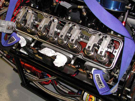
Here is a photo of the prototype. A picture is worth a thousand words.
If you have any questions please call 785-422-8722.